Hello! My name is Tom and I like:
Let me tell you a little about myself and what I do
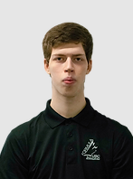
I am studying Manufacturing Engineering at the University of British Columbia planning to graduate in May 2027. I am plan to potentially take a masters in the aerodynamics field post secondary and hopefully become a CFD engineer.
Formula UBC Racing is an engineering design team focused on designing, building, and racing a formula style race car based on a rule set given to us by the Society of Automotive Engineers (SAE). We manufacture almost everything about the car in house and trailer it out to Michigan every year to compete against schools from all over the world. I have been on the Aerodynamics sub-team for 3 years and I’m going into my 2nd year of being the Aerodynamics sub-team lead. I also manage the team’s finances.
A few skills I have developed primarily from Formula UBC and some of my personal hobbies are:
Most importantly, I like to have fun and do what I deem to be “cool” things. As of right now, learning the engineering process of designing, simulating, manufacturing, and validating an FSAE aerodynamics package is the coolest and most fun thing I can do with my time, which results in it taking up most of my weeks.
Here are some of my past projects
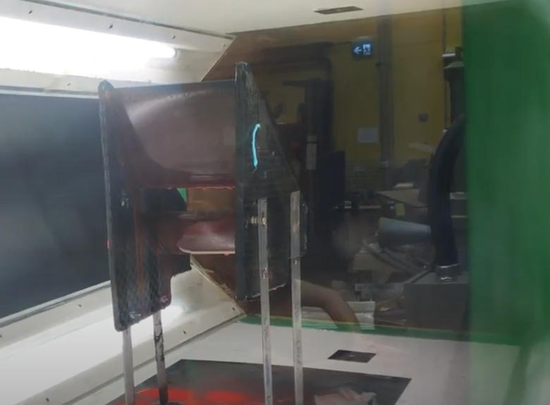
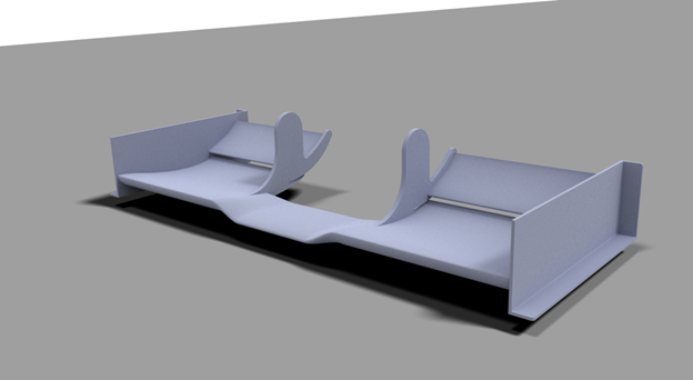
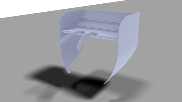

I made the 2023 front wing for Formula UBC Racing on a tight timeline of three months. I used SolidWorks to design the wing, using surfaces for all the wing elements, and solid bodies for the simpler shapes. Star-CCM+ was used to simulate its performance with the k-w SST turbulence model at a wall y+ < 5. HMSWorks was used to toolpath the mould for the wings, and CNC-ed out of MDF. Lastly, pre-preg carbon fibre was laid up on the prepped mould surface, cured, then assembled.
Unfortunately, the member who I assigned the task to disappeared midway through the season, which left me, the aerodynamics team lead, to engineer this crucial component within the tight timeline. In 2022, the team ran a triple element front wing inboard of the tyres and ran dual elements in front of the tyres (as per rules restrictions). However, for the 2023 season, we ran the first ever monocoque chassis, which resulted in me not being able to reuse the 2022 front wing.
The first step for me was to read internal documentation of previous front wings. I knew to manufacture a similar wing to the 2022 year would be not possible given the tight timeline, which meant I had to read about previous geometries of complete dual element front wings.
The front wing had to meet two main objectives; to be easy to remove and install, and to be lighter than the previous year. To account for serviceability, I took advantage of the flat portion of the monocoque chassis to install the front wing with four, easy to access bolts. I then designed the internals of the wing to consist of completely carbon fibre sandwich panel stringers, lighter than the spar and aluminum ribs previously implemented. The wing has a CD of 0.15 and a CL of 0.60.
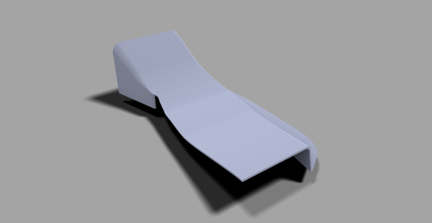
Sandy’s 2023 Side Tunnels was not made by me, but it was a project I assigned two new engineering students I recruited for the 2022-2023 Formula UBC season. It was the first project I did not do myself, but successfully led someone else, while still being heavily involved in all steps of the process. I have never manufactured an aerodynamcis package before this, which meant I had to always be one step ahead ready to help out my members if they requried it.
My approach to leading this project was to first set expectations of my current knowledge as it does not help the team if I pretend that I know everything. Next I talked to each member and asked them what would like like from me in terms of leadership such as step by step instructions, or more general guidance allowing them to figure things out for themselves. Both members preferred the general guidance approach. From there, I simply prompted some ideas of what which directions this project could go and allowed both memebrs to work together and figure out how to work through the aerodynamic engineering design process similar to the Front Wing or Rear Wing. If anyone had questions I encouraged them to bug me at any time and I helped them as quickly as I could.
Through this experience, I discovered how involved I must be in helping new recuits with their projects. Especially since skills such as simulating and manufacturing these complex goemetries are not taught anywhere else. What I plan to do next year is to stagger a few projects such that while new recruits are going through the design phase, there will be some manufacturing happening for projects that senior members have been working on throughout the summer. This will hopefully allow new recruits to see what are the expectations for simulation verification then manufacturing looks like allowing them to consider designing for manufacturability.
I made the rear wing in about 4 months going through legacy documentation, CAD using SolidWorks, CFD using Star-CCM+, manufacturing with carbon fibre making welded aluminum moulds and CNC-ed MDF moulds, and validation through data collection and analysis. The process is very similar to the front wing except for the swan neck investigation.
The three main priorities for the rear wing based on the previous year’s experience are: weight, serviceability, and equal performance. In 2022, the rear wing was held up by 11 rods interfering with anyone who wants to work in the rear section the vehicle, and it took a very long time to dismount, mount, and align the wing. This warranted investigation into a swan neck mounting design.
With a swan neck mount for the rear wing, careful investigation had to be performed to ensure the wing won’t fall off which is a critical failure. This consisted of using fundamental structural theories and our knowledge of composite to come up with a design and layup schedule. The result ended up being a beam like structure. The layup was a sandwich with high density foam as the core, and three plys of unidirectional fibre along the direction of load, and a layup of spread tow on top for good engineering practice. The result that an individual swan neck was able to withstand 1.2kN before internal failure occurs, and from there it slowly becomes weaker and weaker which is a desirable mode of failure.
This was my first project for Formula UBC when school was resumed to be in person after COVID-19. Previously, an idea was proposed to cure aerofoils as one part instead of two halves and adhering them together after the cure. Doing it all in one go would decrease variation between CAD, the geometries that we simulate in the virtual world, and reality, the geometries we make and that actually interacts with the air moving around our vehicle.
After my first few layups, I noticed there were some several defects within the part that disrupted the surface finish, a critical aspect of an aerofoil. I identified the failures as a variety of fibre misalignments and dry spots. I decided to run a few tests of different layup up methods of overlapping the bottom and top halves of the airfoil differently to see if I can produce an acceptable aerofoil consistently. If I couldn’t I knew that the mould geometry would be the main issue and we would have to invest time and resources into redesigning and manufacturing a modified mould.
The conclusions resulted that slightly staggering the inner ply of the carbon fibre for the bottom half to be slightly longer while the top half was slightly shorter fixed the problem most of the time. I was able to produce enough aerofoils that were acceptable to be on the car for the 2022 competition, but it was truly the mould that was too small at the tail edge applying extra forces in plane of the carbon fibre while curing that resulted in most of the issues. For the 2023 season, the moulds were made to account for the thickness of the carbon fibre, and these issues did not appear anymore!
Due to lack of aerodynamic validation methods available to Formula UBC, I have decided to do some research into developing a Flow-Visualization paint for our FSAE purposes. I am using a closed-circuit wind tunnel to test out different recipes consisting of either mineral oil, paint thinner, kerosene, paint pigment, classroom chalk, olive oil, and linseed oil.
The plan here is to test many varieties of paint on a flat plate first, to get a qualitative behavior that I am looking for, then I will use a dual aerofoil element to verify a CFD simulation. I am looking only for the surface flow behavior, not the force measurement since that’s what flow-visualization paint is good for.
As of writing this modal, we have not been able to come up with a good recipe. In reducing the viscosity of the paint for FSAE purposes, the “stickiness” of the paint is not good enough making it drip off the aerofoils. Research into surface energy and spending time acquiring different ingredients is in progress.
Here is how you can contact me